In many cases, we need to use switches that open and close at certain times or under certain conditions of voltage or current. PSpice has many excellent models of transistors, thyristors and other devices that react to changes in a base circuit or a gate input. However, these detailed models of the devices demand a lot of resources. If we are more interested in a circuit's response to switching actions than we are in the behavior of the switches, then simple voltage-controlled or current-controlled switches can readily be used. Another issue is modeling a complex circuit with the demonstration version of PSpice. You may not have enough resources to model the circuit unless you use simpler devices for the switches.
Both of the controlled switches we will present here function by having two values of resistance. One value when the switch is on and the other value when the switch is off. PSpice linearly varies the switch resistance between these two values according to the value of the controlling voltage or current between its two threshhold values. All of these parameters are user-defined in a .MODEL statement.
The part name for the voltage-controlled switch must begin with the letter "S." This is followed by the two switch nodes, (S1 and S2 in the above figure), and the two nodes across which the controlling voltage, Vc, is applied (Vc1 and Vc2). The last item in the list is the model name. We will need a .MODEL statement for the device. There are only four parameters: Ron, the resistance of the switch when it is on; Roff, the resistance of the switch when it is off; Von, the threshhold voltage for turning the switch on; and Voff, the threshhold voltage for turning the switch off. A typical statement for a voltage controlled switch could be as follows:
Sw1 1 2 10 0 Smod
.MODEL Smod VSWITCH(Ron=1m Roff=1MEG Von=1V Voff=0V)
In this example, the switch is connected between nodes 1 and 2. The voltage between nodes 10 and 0 is used to control the switch. When this control voltage is 1V (Von) or greater, the switch resistance is 1 mΩ (Ron). When the control voltage is 0 (Voff) or less, the switch resistance is 1MΩ (Roff). The resistance varies linearly with the control voltage when the voltage is between Von and Voff. VSWITCH is the model type for a voltage-controlled switch while Smod is the model name assigned by the user. You can change any of the model parameters, but zero resistance is not recommended.
The purpose of this circuit is to step down the voltage from the 20 V supplied to the required load voltage of 10 V at the load represented by RL. We will control the switch with a PULSE voltage source (to review the PULSE source, click here). The pulse source will cause the switch to be on about 50% of the time and have a switching frequency of 10 kHz. We will also use an ideal diode based on the TABLE type of dependent source (to review a more complex example of using the TABLE dependent source to model a diode, click here). In a future tutorial, we will explore the details of diode modeling with the more realistic DIODE model available in PSpice.
To summarize, this example uses an ideal switch, an ideal diode (no forward voltage drop), an ideal inductor (no series resistance) and an ideal capacitor (no ESR). It allows the user to study the effects of using different values of inductance and capacitance to filter the output voltage to the desired DC value with minimum ripple. The circuit file for the above circuit is shown below.
Buck Regulator with Vswitch
.SUBCKT Ideal_Diode anode cathode
Vx anode int DC 0V
Ed int cathode TABLE {I(Vx)}=(-0.01A,-30V) (0A,0V)
.ENDS
Vpls 10 0 PULSE(0V 2V 0s 1us 1us 49us 100us)
Rpls 10 0 1MEG
Vdc 1 0 DC 20V
Sw1 1 2 10 0 Smod
Xd 0 2 Ideal_Diode
.MODEL Smod VSWITCH(Ron=1m Roff=1MEG Von=1V Voff=0V)
Lf 2 3 250uH IC=4.00A
Cf 3 0 50uF IC=10.0V
RL 3 0 2.0
.PROBE
.TRAN 1us 1ms 0us 1us UIC
.END
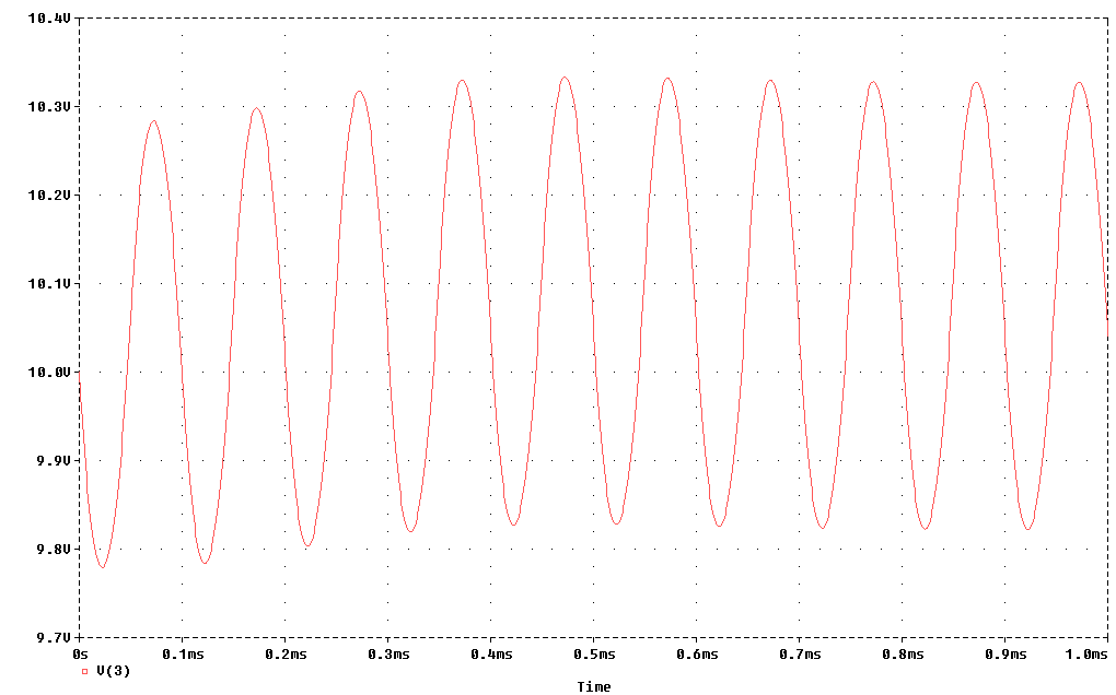
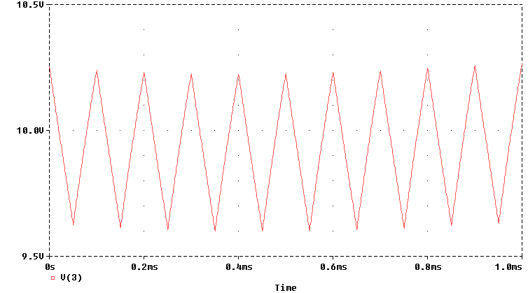
From the output waveform we can see that the simulation ran long enough to achieve periodic steady state. (It helps to choose the initial inductor current and capacitor voltage well.) Also, the amount of ripple agrees with the design equation for the buck regulator, Δvc = Vs (1-d) d2 T2 / 4LC, which predicted 0.5 V (peak-to-peak) of ripple. This amounts to about 5% ripple which would be acceptable for many applications.
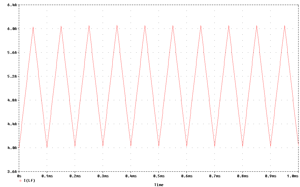
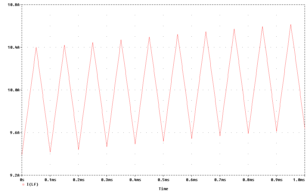
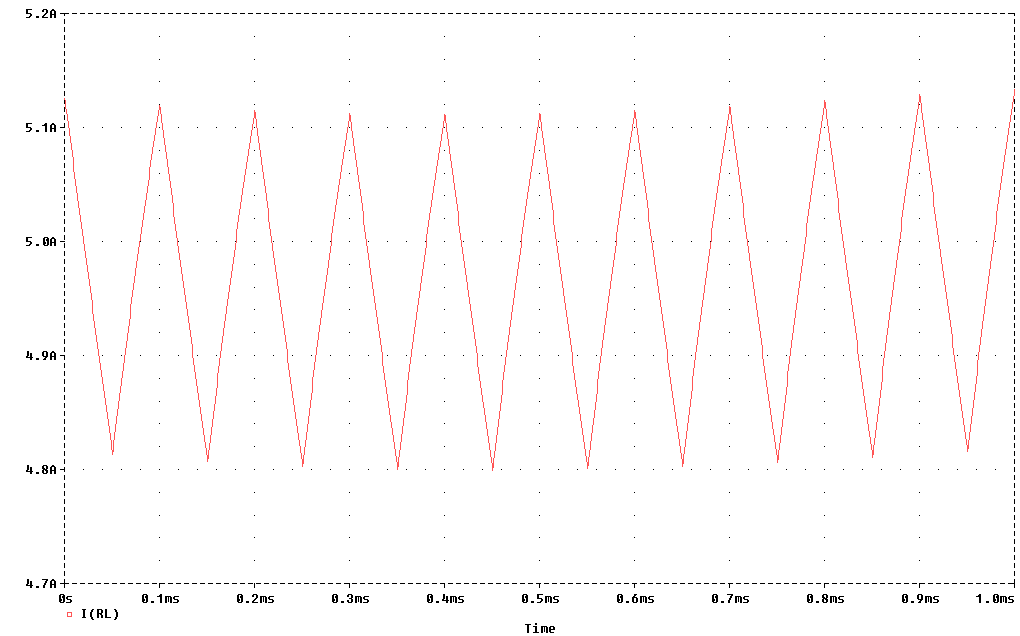
In addition, we can examine another waveform, the inductor current.
The part name for the current-controlled switch must begin with the letter "W." This is followed by the two switch nodes, (W1 and W2 in the above figure), and the ideal voltage source part name through which the controlling current is detected and measured. The last item in the list is the model name. We will also need a .MODEL statement for this device. The model paramenters are similar to those of the previously discussed voltage-controlled switch: Ron, the resistance of the switch when it is on; Roff, the resistance of the switch when it is off; Ion, the threshhold current for turning the switch on; and Ioff, the threshhold current for turning the switch off. A typical statement for a current-controlled switch could be as follows:
Wsw 2 0 Vctrl Wmod
.MODEL Wmod ISWITCH(Ron=1m Roff=1MEG Ion=1mA Ioff=0A)
In this example, the switch named Wsw is connected between nodes 2 and 0. The current through a voltage source named Vctrl is used to control the switch. (Normally, Vctrl is set to zero volts as a source.) When this control current (measured by Vctrl) is 1mA (Ion) or greater, the switch resistance is 1 mΩ (Ron). When the control current is 0 (Ioff) or less, the switch resistance is 1MΩ (Roff). The resistance varies linearly with the control current when the current is between Ion and Ioff. ISWITCH is the model type for a current-controlled switch while Wmod is the model name assigned by the user. You can change any of the model parameters; again, zero resistance is not recommended.
The purpose of this circuit is to step up the voltage from the 5 V supplied to the required load voltage of 10 V at the load represented by RL. We will control the switch with a PULSE current source (to review the PULSE source, click here). The pulse source will cause the switch to be on about 50% of the time and have a switching frequency of 10 kHz. We will again use an ideal diode based on the TABLE type of dependent source.
To summarize, this example uses an ideal switch, an ideal diode (no forward voltage drop), an ideal inductor (no series resistance) and an ideal capacitor (no ESR). It allows the user to study the effects of using different values of inductance and capacitance to filter the output voltage to the desired DC value with minimum ripple. The circuit file for the above circuit is shown below.
Boost Regulator with Wswitch
.SUBCKT Ideal_Diode anode cathode
Vx anode int DC 0V
Ed int cathode TABLE {I(Vx)}=(-0.01A,-30V) (0A,0V)
.ENDS
Ipls 0 10 PULSE(0A 2mA 0s 1us 1us 49us 100us)
Vctrl 10 11 DC 0V
Rpls 11 0 1m
Vdc 1 0 DC 5V
Lf 1 2 250uH IC=9.4A
Wsw 2 0 Vctrl Wmod
Xd 2 3 Ideal_Diode
.MODEL Wmod ISWITCH(Ron=1m Roff=1MEG Ion=1mA Ioff=0A)
Cf 3 0 400uF IC=10.25V
RL 3 0 2.0
.PROBE
.TRAN 1us 1ms 0us 1us UIC
.END
In the waveform below, the output voltage is shown. Periodic steady state has nearly been reached with an average value of 9.95 V. The ripple amplitude is 0.6 volts for a ripple factor of about 6%. This could be improved by increasing the capacitor value. This is a fairly efficient method for doubling the dc voltage.
The inductor (also input) current is shown below. It is approaching its average value of 10 amps. An ideal converter would take in 5 volts at 10 amps and deliver 10 volts at 5 amps.
And we see the output current averaging the required 5 amps below. Some refer to these dc regulator circuits as "D-C Transformers."
With these examples we conclude our demonstration of voltage-controlled and current-controlled switches. Many other applications are possible.